


Fueling the Future: Inside the Brains of a Hydrogen Refuelling Station
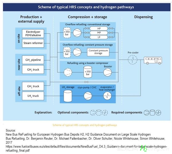
? 1) Hydrogen Refuelling Station (HRS) for buses components:
1.1 Hydrogen supply: on-site hydrogen generation or off-site production, with H2 delivery to the station;
1.2 Hydrogen Compression: to get pressure required for the vehicles;
1.3 Hydrogen Storage: hydrogen stored at the refuelling station;
1.4 Hydrogen Dispensing: transferring hydrogen to the vehicles.
? 2) On-site hydrogen production:
2.1 Water electrolysis:
An electrolyzer is a device that uses electricity to split water into hydrogen and oxygen.
- Proton Exchange Membrane (PEM) electrolyzer
- AEL (alkaline electrolysis) electrolyzers:
- Anion Exchange membrane (AEM) Electrolyzer
- Solid Oxide Electrolyzers Cell (SOEC)
2.2 Steam reforming:
- A steam reformer uses methane and water vapor to produce hydrogen through a catalytic reaction known as steam methane reformer (SMR).
- For carbon-neutral hydrogen production, renewable electricity is required for electrolysis, or biogas methane for steam reforming.
? 3) Hydrogen delivery for off-site production:
3.1 A hydrogen pipeline can transfer high volumes of hydrogen.
3.2 Gaseous hydrogen (GH2 ) is transported in tube trailers at different pressures.
3.3 Highly insulated trailer tanks deliver the Liquid Hydrogen (LH2, -253°C at ambient pressure) from a hydrogen liquefaction plant to the HRS.
3.4. Mass of hydrogen in 1m3:
1 bar (0.1 MPa), 25°C → 0.081 kg H2
100 bar, 25°C → 7.67 kg H2
300 bar, 25°C → 20.54 kg H2
500 bar, 25°C → 30.81 kg H2
Liquid hydrogen → 70.8 kg H2
? 4) Hydrogen Compression:
4.1. Reciprocating Hydrogen Compressors [API 618 and API 11P] are used in low hydrogen volumes, and high hydrogen pressures.
4.2. Centrifugal hydrogen compressors are used for high volume flow and low pressure ratios.
4.3. Diaphragm hydrogen compressors use a membrane to separate the hydrogen from mechanical parts to avoid issues with sealing wear.
4.4. Ionic liquid piston hydrogen compressors use an insoluble ionic liquid to minimise the risk of hydrogen contamination and energy costs by removing seals, bearings, and other moving parts.
4.5. Cryo-pumps or cryogenic hydrogen compressors (CHC) increase hydrogen pressure efficiently and without hydrogen storage. They are more compact and work better than compressors for gaseous hydrogen.
? 5) Hydrogen storage:
5.1. Type I Hydrogen steel tank (300 bar);
5.2. Type II Hydrogen Tank has fibreglass hoop wrap outside and an inner liner of aluminium (300 bar);
5.3. Type III has fibreglass full wrap outside and an inner aluminium liner (700 bar);
5.4. Type IV has an additional plastic wrap inside to seal off the hydrogen (700 bar).
? 6) Hydrogen Dispenser:
- ISO 19880 Series
- ISO 17268
- SAE J2600-3
For reference, see the attached image.
平台声明:该文观点仅代表作者本人,零碳未来网 系信息发布平台,我们仅提供信息存储空间服务。


发表评论 取消回复